Thursday, December 11, 2008

Checkerboard Tissue Information from Bucky Walter

Tom Ryan gave me a presents of 12 sheets of checkerboard tissue. I do not know where he purchased the tissue or the cost per sheet. The tissue was made in Gifu, Japan by the Esaki Model Meg. Co., Inc. Shorty’s Basement is selling Esaki Checkerboard Tissue for $3.50 a sheet. Shorty’s Basement can be found on the Internet at Shorty’s Basement.com.

I am covering a Rambler Free Flight model at this time, so I decided to use a sheet of blue and white checkerboard tissue to cover the rudder. The Rambler is covered with Polyspan. My method for applying tissue on Polyspan which has two coats of thin nitrate dope applied is as follows:

Iron the tissue to remove wrinkles.
Carefully lay the tissue on the Polyspan.
Spray with water.
Use a foam brush and carefully brush out any wrinkles.
Use the same foam brush and apply a coat of dope over the wet tissue. Some slight wrinkles can be smoothed out with your finger.
Let the tissue dry.
Apply as many coats of dope that you desire.

Covering the rudder with the checkerboard tissue I did not have to iron the tissue, it was wrinkle free. It also has a shinny side; Gene Wallock and I decided it had a sealer coat of something applied. I proceeded using steps 2 through 5. I was not too happy. There were many small wrinkles. I was afraid to try to brush the wrinkles smooth. After the tissue dried it was very difficult to see the small wrinkles. So I doped the covering a few times. It looked pretty good. I think all the squares confuse your eyesight and makes looking for wrinkles a little difficult.

I decided to talk with Gene Wallock about my covering method. Gene told me he uses acetone to attached the tissue around the edges, spray with water and let dry, then apply the dope. Gene’s method is a better method, except for using acetone to attach the tissue. I tested a scrap piece of checkerboard tissue with acetone. The acetone did not smear the shinny side of the tissue. When I lifted the tissue up off the surface, the blue was beginning to smear. So if you tried to move the tissue to reposition it was going to be very messy.

This method works.

Use a glue stick around the edges. I use an Avery Permanent Glue Stick – white color.
Carefully lay tissue on the Polyspan and press the tissue on the applied glue. You can lift the tissue up and reposition it, if required.
Spray with water.
Let dry.
Dope the tissue as required, I use a foam brush.


UPDATE
Hi Guys,
A few months ago I brushed clear nitrate dope over checkerboard tissue and had it smear a little. I brushed very lightly. But it did smear.
Since then Tom Ryan was informed that if you put the shinny side down against the frame work, then you can brush the dope on the tissue and it will not smear. Reported in SAM35 Speaks
I just used that procedure and the checkerboard tissue did not smear!
Yeah!!
I told Tom about my problem. He put it on his blob page and he got a correct reply to the problem.
Computers can solve a problem or two. That is, if you know how to use a computer.
Bucky

I should add that the checkerboard tissue from Peck Polymers was of two type: Black & Yellow and everything else.
The former appears to have started as dyed yellow tissue with black squares then dyed into it. The others look as thought they started as one color and then had shiny square painted on. Bucky has not tried the yellow & black yet.


Friday, November 7, 2008

Bucky Walter's Ramblings (part 1)


Hi Guys,


Some construction photos. I used Jim O'Reilly and Bruce Augusta plans, plus Bucky Walter modifications.


I beefed up the fuselage construction. I dropped the fuselage a few time and kept finding broken glue joints. The Old Timers were built to glide to a landing, not dteeing. This model should weigh about 2 1/2 pounds, so when it DTees it will drop like a rock. The tail section is beefed up from the original and the nose section along with a rubber band engine mount. Hopefully this will relieve the shock of a hard landing or DT. I found the model to be very nose heavy. Therefore the battery box is installed in the rear of the fuselage. After the battery box was installed the model was still a bit tail heavy; so the Texas Ultimate OT Timer was installed in the rear of the fuselage. The model is still a slight bit nose heavy; I hope the covering and the dope on the rear end of the model will bring into balance.


The stab did not want to raise up into the DT position of 50 degrees. It required a lot of rubber bands. Finally had to straighten the leading edge of the stab, then it popped up with fewer rubber bands. Another problem occurred, the closeness of the timer to the stab would not let me install a stop for the line which attaches to the timer. If you let the line flyoff, it will disconnect from the tension rubber bands and go flying off to who knows where. An additional line was connected to the timer line secured to the side of the fuselage near the timer. This will prevent the line from flying off the rubber tension hooks. That took a little while to figure out.
Ready to start building the wing. It will be beefed up to with stand the hard DTees


Monday, October 13, 2008

A Dozen Aeronautical Myths

A Dozen Aeronautical Myths
(from www.vintagents.com)

One often overhears comments about the behavior of model aircraft at the field, and while the remarks are about models, they would also apply to full size machines.
Some of these expressed ideas reflect common myths, so I dug into my memory from 40 plus years ago for the explanations of why they are wrong, and present them for discussion.

Myth 1:
A model will tend to weather cock into wind during flight.

Assuming a steady (non gust) wind, the aircraft can do no such thing, short of being anchored to the ground in some way. A fuller explanation follows below at myth 4.

Myth 2:
A model will stall if it flies too slow.

This one can be correct, but not necessarily so. It is not speed that causes a stall, but separation of the airflow from the wing. This means an aircraft can stall at high speed, e.g. a snap roll, or not stall at zero speed, e.g. the top of a hammer head (sometimes called a stall turn despite no separation burble). Think of stalling as an angle of attack (around 16 degrees), rather than speed.

(By the way, a 60 degree level turn increases your stall speed by 41%). It is the higher angle of attack in a turn, that can cause a stall, leading into a low speed snap roll

If you lose power, you are unlikely to stall if you get the nose down below level flight. Warning signs to get the nose lower come from having a lot of up elevator applied. It means you are approaching 16 degrees.

Myth 3:
The more stable an aircraft, the better it is at aerobatics.

Quite the opposite. A stable aircraft wants to keep doing what it is designed to do, normally regain level flight if disturbed from it. You don't need this stability fighting you if you are trying to make the aircraft follow your commands. A good trainer should be stable, but few are these days.
Neutral stability best serves the aerobatic pilot since the machine keeps doing what was last commanded to, with no deviation.
Unstable aircraft are usually beyond human control, as they increase any deviation input given to them. Too far back a C.G. can make a simple up command turn into an unwanted loop for example. Modern fighter jets are unstable in order to attain rapid response, but need a computer to fly them.

Myth 4:
Turns down wind are more dangerous than turns upwind.

In some ways this is true, but not for the usually given reasons. In a turn downwind, a gust will tend to roll you on your back since the high wing usually presents more under wing area to the gust, than the low wing.

Secondly, your increased ground speed downwind makes a prang take place at higher ground speed than turning up wind.

Thirdly, the increase in ground speed gives the illusion of a higher airspeed, tricking one into slowing the airspeed, perhaps to the stall.

That said, the aircraft has no way of keeping track of it’s relationship to the earth below it. This is an important point to remember and this enlarges on the explanation on Myth 1. Assuming a non changing wind, once the machine is airborne, the ground relationships cease. It is in a river of air, and the motion of the river over the earth, doesn't affect it's flight characteristics.

One way to get this clear, is to imagine you are in a free floating balloon watching a model circle around you. The balloon may be doing 100 kph over ground, but you won't fell a breath of wind. Neither will the model circling you, other than it’s own airspeed.

Only when a machine reemerges from the "river" of air, and touches the shore do we need to worry about the earthly relationship.

Another example: Imagine you are on a train moving at speed. As you walk in the direction of travel, your speed over the ground is increased by the speed of your walk, and conversely, if you walk to the back of the train, your speed over the ground is reduced. The speed of your walk in the train, is not affected by the speed of the train. If you bump into someone, your momentum is relative to the train, and it doesn’t matter which way you walk.

Just as you are in the moving train, the aircraft is in the moving air mass. In the example above, the aircraft speed is equivalent to your walk speed, and the air mass (wind speed) is like the train moving over the ground.

Consider a 180 degree turn in still air. It involves reversing ground speed from say + 100 North to - 100 South, a relative speed change of 200 within the time of turn.

Now imagine you are flying into a headwind of 100 going North,. Your ground speed is now zero. You now again do a 180 degree turn, in the same time frame. Your final ground speed is 200. Once again, a relative speed change of 200 within the time of turn.

Notice, the aircraft undergoes the same accelerations within the time of the turn. It make no difference because the wind is blowing. As you turn down wind, it may help you to visualise the wind is helping carry the aircraft down wind and accelerate it over the ground.

Myth 5:
The model can make a tighter turn if it slows down.

Look at our pylon champ for an answer to that one. It again comes down to angle of attack and it is the stalling angle of your machine that determines it's minimum radius turn. You can turn at the minimum radius at more than one speed, but the faster the speed, the more bank is required which in turn means you increase angle of attack. If one stalls at these speeds, a snap roll usually results. The increased angle of attack required in a level turn will slow you down if you don’t add power.

Myth 6:
A high wing gives pendulum stability.

This is misleading, because a pendulum is fixed to a support, whereas the aircraft is not fixed in any way. What happens is that as the aircraft banks, It sideslips towards the low wing, and it is the retarding effect of this relative airflow on the top wing that rights the plane (see myth 7).

Myth 7:
Dihedral works because the horizontal lift component of the lower wing is greater than the other.

Yes, partly but more is involved. Imagine you can slide the model along a wire through it's C.G., and it's not hard to see that while the above effect will slow a rotation, it won't stop it, and certainly won't bring the model upright. Once again, it is the sideslip that increases the lift on the lower wing and levels it. As the wing drops, the model slides in that direction, causing a greater relative angle of attack and lift on the lower wing. The opposite wing has a lesser angle to the relative airflow.

Myth 8:
"Dual servo rate should be low for strong winds and high for light winds". (After hearing this, I assume the proponent thinks that strong winds give more airflow over the controls and less control deflection is thus required.)

If one realizes that an airplanes "wind" is due to it's motion, and not the wind speed (when airborne, remember it is in a river of air), then different rates of throw are not involved with wind speed although they are with airplane speed through the air (relative wind).

Myth 9: Big vertical stabilizer (fin) means directional stability.

If we remember that an aircraft will sideslip towards the lower wing in a bank, the relative air stream creates side forces either side of the C.G. These can either yaw the model into the slip or out of it. Too large fin acts like a weather cock during the slip, and tightens the turn. The end result is the nose dropping and a spiral dive. The perfect size fin will balance the area ahead of the C.G., so that the yaw is appropriate for the sideslip involved. Too small a fin will yaw a machine out of the turn.
It is the rudder effect that turns (yaws) the airplane (else it would crab in a straight line but wouldn't turn), despite the fact you may only use aileron input. The bank causes the machine to sideslip, which brings in the rudder yaw effect.

Myth 10:
A model will glide farther if it is light.

Assuming no wind, the angle of glide relates to the lift and drag of the machine. Without drag you would glide horizontal indefinitely and without lift, you have a vertical descent (don’t we know). The actual glide angle is thus a ratio of these two (Lift to Drag), and not related to weight. Wind has an effect on the angle over the ground, but not through the "river of" air. The heavy model will reach the ground sooner, since it glides at a higher speed, but both will glide the same distance in still air.

The minimum sink speed of a model is flown slower, near the maximum angle of attack (not the faster best distance speed), since one is more concerned with lift than speed. Here a light model will glide a longer period than a heavy one.

Myth 11:
A model will gain the most height in a given time, if we climb it at the best angle of climb.

There is a difference between angle and rate of climb. The first compares altitude to forward distance and is affected by wind, the second compares altitude to time and is not influenced by wind. Best rate of climb is done faster than best angle of climb.

Myth 12:
A headwind will slow a model more than an airliner.

If we go back to the "river of air" concept, one will find it easier to grasp the picture that everything in the "river" is carried along at the same speed. Hence a ten knot headwind will take 10 knots off the model and airliner speed, equally.

Now let the arguments begin.

Arnold

Saturday, September 13, 2008

The 1940 Reich Albatross


Gordon Pearson's model at 77 Toledo Show


Working with Light Polyspan


LIGHT POLYSPAN

6’ x 39” $13.00


THERE IS A GLOSSY AND LESS GLOSSY SIDE. THE SMOOTH GLOSSY SIDE IS THE OUTSIDE (UP). Run grain spanwise!


APPLY AS YOU WOULD FOR SILKSPAN BY PREDOPING THE PERIMETER WITH TWO COATS OF DOPE AND MORE COATS ON THE BOTTOM OF THE RIBS IF THE WING IS UNDERCAMBERED. LIGHTLY SAND THE DOPED AREAS.

CUT THE MATERIAL OVERSIZE, PARTICULARLY AT AN ELLIPTICAL SHAPED TIP, ETC.

APPLY BY DOPING THRU THE MATERIAL. I NORMALLY USE THE MAIN SPARS FOR FIRST ATTACHING IT, THEN DOPE THE LEADING OR TRAILING EDGE. NEXT, PULL ANY EXCESS MATERIAL OUT. IT DOESN’T HAVE TO BE TIGHT AT THIS TIME. DOPE EACH UNDERCAMBERED BOTTOM RIB AND RUB DOPE THRU THE POLYSPAN, ADHERING IT TO THE RIBS .

CUT THE EXCESS AROUND THE PERIMETER SO YOU WILL HAVE AN OVERLAP OF ABOUT 1/8”.

USING A MONOKOTE TYPE IRON, ROLL THE EDGES TO HELP THE MATERIAL FOLLOW THE CONTOUR. THEN DOPE IT DOWN AND RUB THE DOPE IN.

DO THE SAME FOR THE TOP ON THE WING. WHEN DOING AN ELLIPTICAL TIP, TACK DOPE SEVERAL SPOTS ALONG THE TOP AS YOU WOULD FOR MONOKOTE. ADD WEIGHT OR HAVE SOMEONE ELSE HOLD THE WING. THEN WHILE PULLING ON THE EXCESS WRINKLE AND HOLDING IT OFF THE SURFACE OF THE WING, HEAT IT WITH THE IRON AND IT WILL STRETCH--AND THEN PUSHING IT DOWN WITH THE IRON, IT WILL CONFORM TO THE CONTOUR.

THEN DOPE AND TRIM THE EXCESS.

THE DOPE WILL SHRINK THE MATERIAL BUT I USE THE IRON TO TAKE OUT ALL THE WRINKLES BEFORE DOPING IT.

PUT TWO TO FOUR COATS OF DOPE, PREFERABLY BRUSHED ON With A Foam Brush!, Thinned about 50%. (DON’T THIN TOO MUCH FOR THE FIRST TWO COATS) THEN IF YOU WANT COLOR, USE THE POLYSPAN DYE, MIXED 1 PART DYE, 1 PART CLEAR BUTYRATE DOPE AND TEN PARTS BUTYRATE THINNER AND SPRAY THIS ON.

(NITRATE DOPE AND THINNER DOES NOT MIX WELL WITH THE POLYSPAN DYE) USE PARKS OR SUNNYSIDE EPOXY & LACQUER THINNER FOR NITRATE DOPE, AVAILABLE AT HOME DEPOT AND TRU-VALUE

SPRAY ON A SEALING COAT OF DOPE. JAPANESE TISSUE OR COLORED DOPE CAN NOW BE APPLIED FOR TRIM IF DESIRED. THEN I BRUSH ON AS MANY COATS OF DOPE TO GET THE GLOSS I WANT (USUALLY 6-7 COATS) TOTAL.

APPLY FUEL PROOFER IF NITRO FUELS ARE GOING TO BE USED.

I SELL THE DYE. SEE MY LIST, SASE OR EMAIL ME FOR IT: samchamp@jetbroadband.com

Larry Davidson

More Polyspan covering techniques are taught by Dave Platt in his B2B (Back to Basics video)www.daveplattmodels.com/Video/index.htm

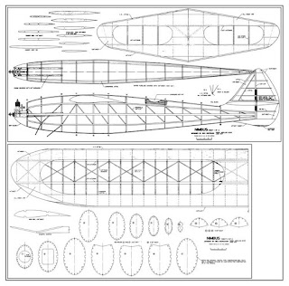
Shereshaw Nimbus


as seen at the Toledo Show


Friday, August 29, 2008

Jap Tissue over Polyspan technique


Cover with Polyspan, shrink and apply 2 coats of dope.
Sand with 600 wet/dry paper to eliminate fur.

Attach tissue like the Polyspan wasn't there.
Use Acetone through the tissue and activate the dope on the Polyspan. Be very careful not to spread it all over.
Water shrink the tissue and let it thoroughly dry.
Brush on a light coat of Acetone to attach the shrunk tissue to the doped Polyspan.
Use a Monocoat iron to eliminate any wrinkles.
Apply two coats of thin dope and re-check for wrinkles. Add a third coat of thin dope to finalize.
If you just want to add tissue letters, just tack them down with Acetone. If they're smooth, apply a light coat of Acetone and use the iron to eliminate wrinkles.

Thermals,
GOD Bless America


Gene Wallock

Thursday, August 28, 2008

Getting ready for the SAM Champs


Here's Dad's new RC-1 yet to be flown. Super Tigre .40 rear rotor.


Wednesday, August 13, 2008

Lesson from Tandy


This afternoon after I got the Bomber and the Airborn cleaned up from flight testing, I unbolted the SuperTiger G21/35 from the Fubar 600X airframe and removed the crankcase pressure line. While this line into the tank was not completely stopped up, it had a thick sticky residue on the inside. So I hooked up a line from the engine's crankcase pressure fitting and ran it into a bowl of water as shown below. With the glow plug removed, I spun the prop, but there were no bubbles produced in the water. This indicated that the pressure fitting screwed into the upper left corner of the back plate was stopped up.

I removed the pressure fitting from the back of the engine and found it was completely clogged up with a dark brown "grunt" that looked a lot like hardened varnish. Hanging dormant for four years had allowed the small .018" hole in the fitting to become sealed over. After soaking the pressure fitting in Acetone for about an hour, I used a .018" drill bit and reamed out the hole in the pressure fitting as shown below. Then I cleaned up the pressure fitting inside and out.

I screwed the pressure fitting into the upper left corner of the back plate and reinstalled the engine in the Fubar airframe. I filled the fuel tank with alcohol and put on the prop, but left the glow plug out. I put a black tubing extension on the fuel line and ran the end into a bowl as shown below. I spun the prop and the crankcase pressure pumped the tank completely dry! Wa-La, the problem is now fixed.

The lesson learned in this exercise is that if you let an engine set unrun over a long period of time (years), you need to clean out the small .018" hole in the pressure fitting before you try to run it again. Now I need to go back out to the field soon and test fly the Fubar 600X. I also need to practice the climb out on both the Airborn and the little Bomber until I can keep them in the groove up to the 35 second engine cut off time and also work on my transition..........................Tandy

Tuesday, August 12, 2008

Flying at the Shelby Airport 8-12-08

Hi Guys,

Gil Morris and I tried to fly today at the Shelby Airport. Gil did some test glides on his folding wing model. He has to fly it at a larger field. The Albatross give him some problems with the ignition system. One problem occurred when the hi tension lead broke at the solder connection to the coil. I (Bucky) glued it back on with thick CA. Bingo he got spark and the engine ran in short bursts. There is another problem which was not solved on the field. No flights on the Albatross.

I test glided the Super Phoenix several times. I had to shim up the leading lead of the wing about 3/8 of an inch. in order to achieve a flat glide. Also add a 1/16 shim under the trailing edge of the stab. This shim screwed up the locking shims for the rear of the stab. Which also caused the rudder to twist to the right very slightly due the DT Rubber Bands. Well we had a glide lets try the first power flight. As you can see from the photos the model banked sharply to the right and came right back to me. Luckily the engine quit running but I hit the ground and the model crashed in front of me. One bent landing gear. No problem to fix.

All day long I kept adding left thrust and removing the incidence in the wing. As the flights got longer the glide showed a slight stall. Finally I was down to 1/16 incidence in the wing and removed the 1/16 shim under the stab trailing edge. This lock the rear shims back in place and the rudder back at natural. Gil told me to increased the engine run time. I was using an old Elmic timer. It was a pain to try to set a time. It took about an half hour to set a repeatable time. We wanted to get a higher altitude so we could check the glide.

Well we got a higher altitude but the glide was straight as an arrow and heading towards the hangers. Bingo it hit the front of the hanger just below the roof. The wing popped off and slide on the roof and the rest fell to the ground. Damage - the left metal motor mount bent slightly.

Things to do:

Straighten the motor mount.

Order a Texas Timer. It is on order!

Rest up from one hectic day.

I was so tired that Gil chased my second last flight. He is in his eighties, I am in my late seventies.

End of flying report.

Bucky